 Documentation
 Download
 News
News Gallery
 Contact
Graphical user interface
The graphical user interface (GUI) for the IPLT diffraction processing pipeline is started by using the iplt_diff_manager command. If the GUI is started in a folder containing a IPLT diffraction project, the project settings are automatically loaded. Otherwise the GUI presents the options to create a new project or to choose a project in a different folder.
The GUI is organized into three panels labeled project, diffraction pattern, and merge. At the bottom of the GUI a slider allows to set the verbosity level for the logging.
Project panel
The project panel displays information relevant to the entire project and allows changing project-wide parameters. It also allows addition of new diffraction patterns, definition of the global beam stop shape and project wide processing and merging of diffraction patterns.
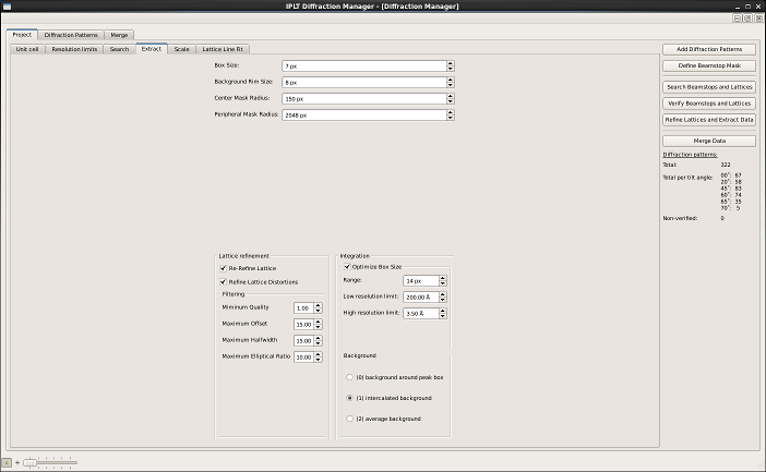
Figure 1: Project panel
Diffraction pattern panel
The diffraction panel displays a list of diffraction patterns on the left side, shows indicators for their processing status and displays RFriedel factors for fully processed diffration patterns. The checkboxes in the first column of the diffraction pattern list can be used to exclude patterns from processing and merging. The center part of the panel allows to override the default processing parameters for single diffraction patterns. The list of buttons to the right allows the user to run individual processing steps manually and to assess the processing results using the data viewer. The list on the bottom right gives access to the log files for the individual processing steps.
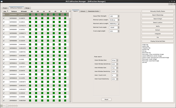
Figure 2: Diffraction pattern panel
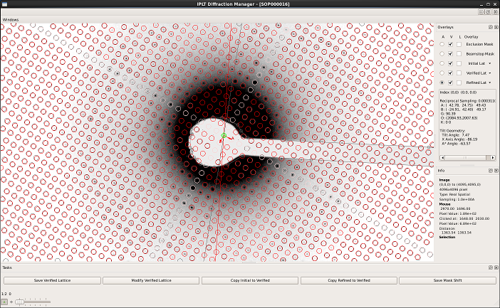
Figure 3: Data viewer
Merging panel
The merging panel allows the merging of the extracted diffraction data into a 3D data set. A new merge can be created clicking New Merge Directory and providing an unique suffix identifying the folder. The currently active merge and refinement round can be selected using the pulldown menus on the top left. The list of diffraction patterns on the left side displays the merging R-factors, the scale and B factors and the tilt geometry for each pattern for each round. The checkboxes allow the inclusion or exclusion of diffraction patterns from merging and refinement. The center part of the merging panel allows to override the processing parameters for the currently active merge. The list on the bottom right allows access to the merging and refienment log files. Graphical plots of the results from the scaling and lattice line fitting can be viewed by pressing Check Scaling and Check Lattice Line Fit respectively.
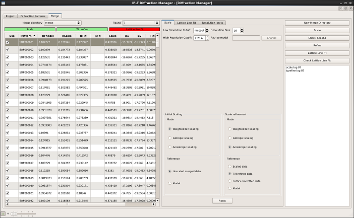
Figure 4: Merging panel
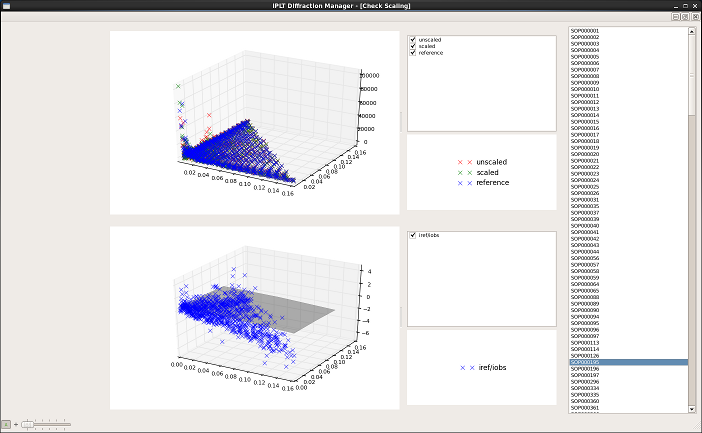
Figure 5: Scaling widget
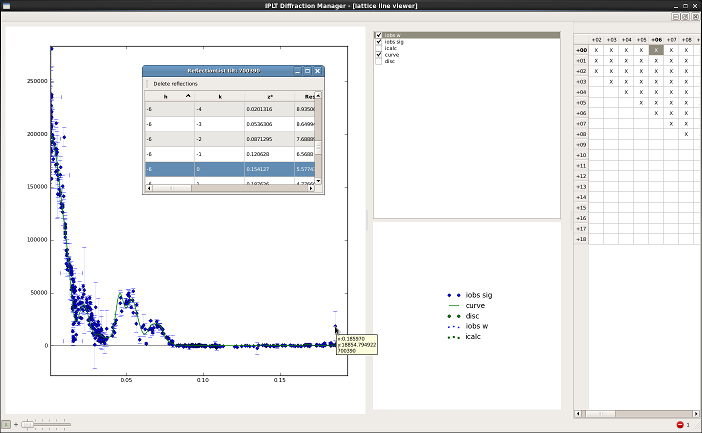
Figure 6: Lattice line viewer