Diffraction data extraction
Overview
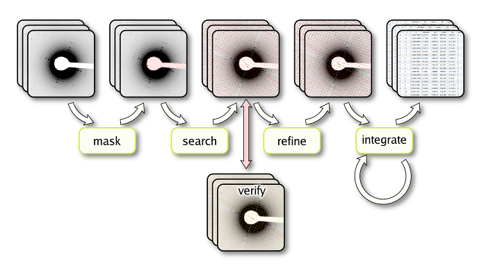
The diffraction data extraction process has four distinct steps. It comprises positioning of a beam stop mask, search for reflection peaks, assignment and subsequent refinement of the lattice, and background-corrected integration of the intensity of each reflection peak (figure 1).

Figure 1: Data extraction overview
Determination of the beam stop postion and masking of the beam stop
The polygonal beam stop shape that was defined during project setup is automatically positioned for each diffraction pattern to cover the beam stop area and exlude refleciton peaks too close to the beam stop from further processing.
Lattice search
The second step in the diffraction data extraction is the automatic search of the lattice in the form \vec{l}=\vec{o}+h\vec{a}+k\vec{b}. Based on the the strongest diffraction reflections an initial lattice is determined automatically. The correct indexing of the lattice is determined based on the information about the nominal tilt parameters known from data aquisition at the electron microscope. The lattice origin is determined based on the minimization of the difference between Friedel related reflection peaks.The correct indexing of the lattice can be verified at this point using the graphical user interface.
Lattice refinement
The initial lattice can further be refined by taking the peak position for all reflection peaks into account. In addition to the refinement of the lattice vectors and the lattice origin, the algorithm also provides the option to determine and refine parameters for the correction of barrel and spiral distortions affecting the lattice (see lattice documentation for explanation of the distortion parameters).
Data extraction
After lattice refinement, the reflection intensities are extracted by integration over the diffraction reflections and correction for the background contribution. The radius of the integration area is automatically optimized to minimize the RFriedel factor for each diffraction pattern.

 Documentation
 Download
 News
News Gallery
 Contact