 Documentation
 Download
 News
News Gallery
 Contact
Project management
The IPLT diffraction manager consists of three main panels. The first panel (figure 1) contains all project-wide parameters and information. It also contains the controls for the very high-level project-wide data processing.
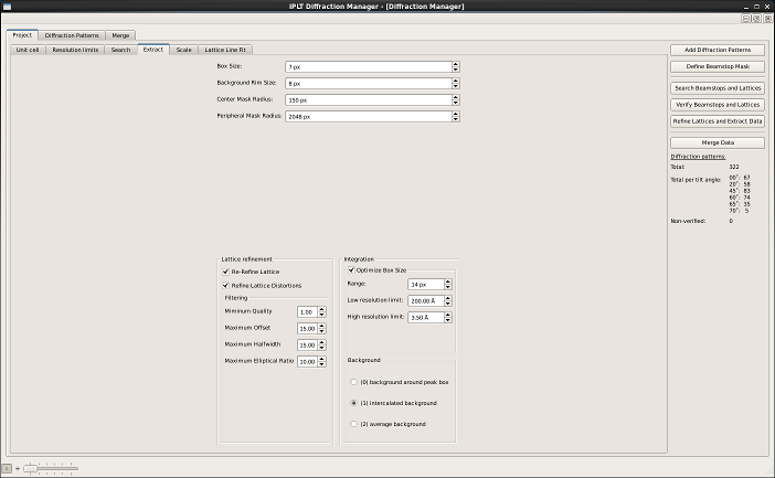
Figure 1: Project panel
Add diffraction patterns
New diffraction patterns can be addded at any time during a project by using the “Add diffraction patterns button”. The file browser allows to select single or multiple (by pressing Control and Shift) diffration patterns. Once a set of diffraction patterns are opened, the import dialog (see figure 2) will be shown, where one can check if the nominal tilt angle and image number were correctly determined for all files. IPLT uses the file name format AAAXXYYYY, where AAA is a three-letter prefix unique for each project, XX is the nominal tilt angle of the corresponding pattern and YYYY is the image number. If the original files don’t follow this naming convention, IPLT will try to guess the correct nominal tilt angle and image number. The tilt angle and image number for a pattern can be modified by double clicking on the numbers in the tilt angle and image number column. Alternatively the nominal tilt angle can be changed for all diffraction patterns and they can be renumbered using the buttons on the top.
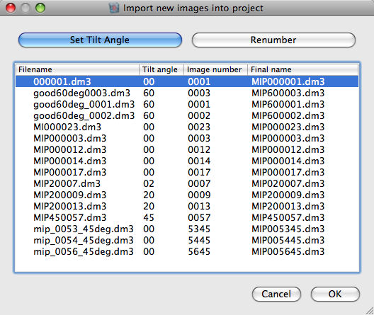
Figure 2: Adding diffraction patterns
Define beamstop mask
The shape of the beam stop has to be defined manually. Later on this information is used to automatically detect the beamstop position for each diffraction pattern. Selecting “Define beamstop mask” opens a Data Viewer displaying the first diffraction pattern and a mask overlay. The mask overlay can be used to create new polygon mask or to modify and move an existing polygon mask. Every interaction with the mask overlay is done by pressing Control together with different keys or mouse buttons. On OS X the Control key is replaced by the Command key.
- Creating a new mask
- Control+Shift+Left Mouse Button: Add a new point to the masking polygon
- Control+A: Accept the new mask
- Control+R: Reject the new mask
- Modifying an existing mask
- Control+Left Mouse Button: Move a point of the polygon
- Control+Right Mouse Button: Move the whole mask
The mask overlay can be used to create a new polygon mask tracing the contour of the beamstop. The mask is saved by selecting “Save global beamstop mask”.
Search beamstops and lattices
“Search beamstops and lattices” allows the automatic determination of the beam stop position and the crystal lattice. The diffraction manager automatically detects and skips patterns, for which these were already determined.
Verify beamstops and lattices
“Verify beamstops and lattices” displays all patterns with non-verified lattices for visual inspection and manual correction (if necessary).
Refine lattices and extract data
“Refine lattices and extract data” refines the lattice and extracts the reflection data for all non-processed diffraction patterns.
Merge data
Merge data creates an initial merged data set that can be further refined using the merging panel.